E-mail seo@sino-purification.com

Time:2026-05-21 11:58:56 Reading volume:
Overview:
Maintaining the dielectric strength of insulating oil is a cornerstone of enterprise data center reliability. During the operation of vacuum oil purifiers (insulation oil filtration machines), precision temperature control directly dictates both purification velocity and the thermal stability of the fluid asset.
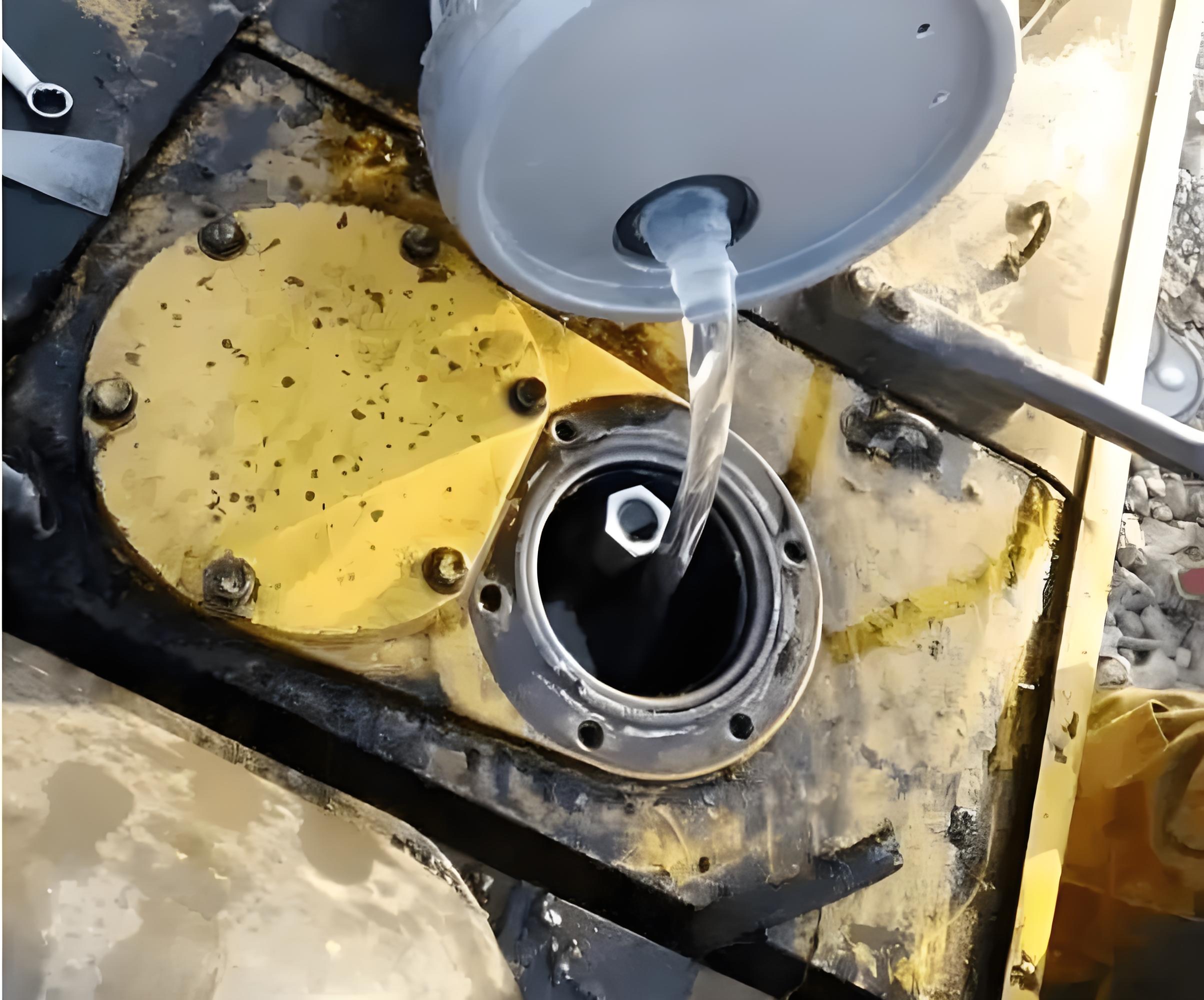
For optimal moisture extraction, degassing, and particulate filtration without risking thermal degradation, operations teams should adhere to the following operational envelopes:
Target Operational Range: 50°C to 65°C
Critical Safety Window: 45°C to 70°C
Operating outside the validated thermal boundaries directly compromises fluid dynamics and vacuum system efficiency.
| Operational Zone | Temperature | Physical Mechanics & Infrastructure Impact |
| Sub-Optimal | Less than 45°C | High Viscosity Dynamics: Elevated fluid viscosity impedes fluid-gas boundary separation. Dehydration and degassing efficiencies drop exponentially as water molecules remain trapped in the tight oil matrix. |
| Optimal | 45°C to 70°C | Peak Fluidity & Volatilization: Ideal kinematic viscosity allows effective moisture vaporization under vacuum conditions. Filter media operates at rated particulate-capture efficiency with minimal differential pressure. |
| Critical Risk | Greater than 70°C | Accelerated Thermal Degradation: Triggers rapid oil oxidation, resulting in asset-damaging acids, sludge formation, and a catastrophic drop in dielectric breakdown voltage. Shorter lifecycle for both fluid and equipment seals. |
Thermal baselines must be adjusted dynamically based on the current chemical and physical state of the incoming insulation oil.
[Fluid State Baseline] ──► New/Low Moisture: 50°C - 55°C (Preventive Maintenance)
                       ──► Routine Processing: 55°C - 65°C (Optimal Balance)
                       ──► Aged/Highly Contaminated: 65°C - 70°C (Max Extraction)
System Architecture Note: These setpoints assume standard two-stage vacuum distillation setups. For standalone coalescence separation or unique chemical reclamation systems, hardware-specific documentation supersedes these general boundaries.
To mitigate thermal shock and optimize energy expenditure, operational teams must enforce the following execution sequences.
Initiate full oil circulation loop through the purifier for 3 to 5 minutes before energizing any heating elements. This prevents stagnant oil pockets from localized thermal cracking.
Program target temperatures using incremental stages (e.g., initial baseline at 45°C, shifting to operational 55°C–65°C only after flow rates stabilize). Never apply maximum thermal load to cold oil.
Monitor the system as vacuum pressures stabilize near -0.09 MPa. If the sight glass indicates erratic boiling or vacuum pressure fluctuates, increment the thermal target by +5°C to match the water vaporization curve of the current vacuum depth.
Ensure automated logic or manual operators terminate heating if temperatures cross 75°C. Continuous operation beyond this ceiling causes irreversible degradation of the hydrocarbon chains.
Sub-Zero / Cold Weather Environments: Fluid viscosity will be significantly higher at startup. Deploy low-density, low-power pre-heating stages to bring the fluid bulk temperature to a minimum of 30°C before initiating high-throughput vacuum cycles.
High-Altitude Topographies (≥2000m): Due to decreased ambient atmospheric pressure, the boiling point of water drops. A lower thermal target of 55°C to 60°C is highly efficient for complete dehydration, reducing facility Power Usage Effectiveness (PUE) overhead.
When control loops drift outside nominal metrics, utilize the following diagnostic matrix to isolate root causes.
| Telemetry Symptom | Potential Root Cause | Corrective Action Path |
| Thermal Stagnation (Cannot reach setpoint) | • Heating element array failure. • Relayed thermostat calibration drift. • Volumetric flow rate mismatch. | 1. Isolate and test individual heating element resistances. 2. Recalibrate RTD/temperature sensors. 3. Verify oil level and pump RPM. |
| Thermal Instability (Temperature hunting/oscillations) | • Erratic fluid inflow rates. • PID loop tuning mismatch. • Faulty thermistor feedback loop. | 1. Stabilize supply-side fluid delivery valves. 2. Tune PID loop parameters for specific fluid volume. 3. Inspect and replace shielding on sensor cables. |
| Degraded Dehydration Output (Nominal temps, poor moisture extraction) | • Vacuum system leak rate too high. • Mechanical seal degradation. • Non-uniform heater array distribution. | 1. Execute vacuum hold test to locate leaks. 2. replace degraded viton/silicone seals. 3. Map heater surfaces with infrared thermography to check for dead zones. |

Optimizing critical infrastructure performance relies on three rigid boundaries:
Target Execution Window: Keep operations strictly locked between 50°C and 65°C.
Strict Procedural Order: Flow control must always precede thermal load.
Environmental Awareness: Scale temperature down at high altitudes and scale up slowly in sub-zero deployments to preserve asset health and optimize energy profiles.
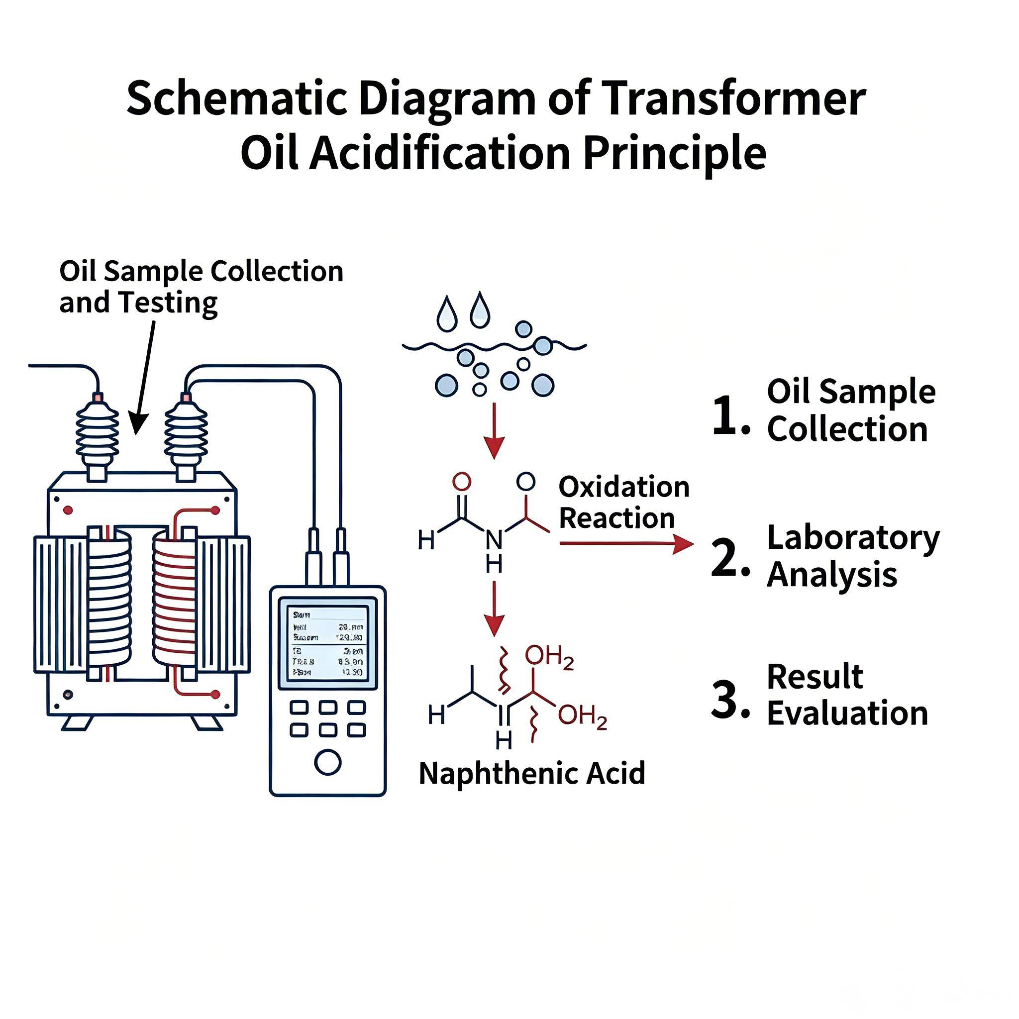
Combating Transformer Oil Acidity: From Diagnosis to Adsorption Reclamation

Mitigating Water Ingress in Turbine Oil: Thermodynamic Benefits of Vacuum Dehydration
Turbine Oil Purification: How to Solve EHC Fluid Degradation Issues
Troubleshooting Oil Purifier Overheating: Causes and Solutions

Does turbine oil purification solve the problem of free water?


